Garrattfan's Modelrailroading Pages
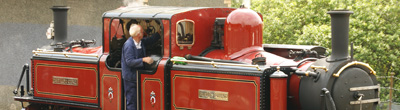
Fairlie Merddin Emrys
6.4 Cab
| The final step in the assembly of the "hulk" of the locomotive is assembling the cab. Much of the cab cannot be fitted permanently yet. During the detailing phase the cab interior must be accessible so in this last assembly step the cab roof and the cab side sheets are made to fit but not soldered into place. It is important to remember this because you will have a hard time removing them if you forget. | |
Tip |
|
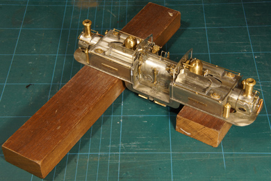 |
Before continuing building here is a little tip which will make your life easy. From now you will be detailing the superstructure of the loco more and more. I found it easy to work on two wooden blocks. This prevents the model from tipping when you work on the front ends. |
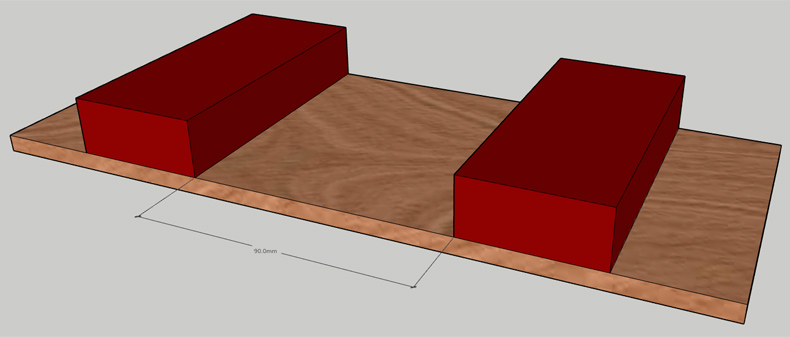 |
A more sophisticated working jig would be to glue the blocks on a sheet of plywood. It prevents them from spreading apart and gives you a very sturdy base to work on your model. I did not make this jig but in hindsight I might have wanted to. |
Cab |
Fig. 110 from the manual. |
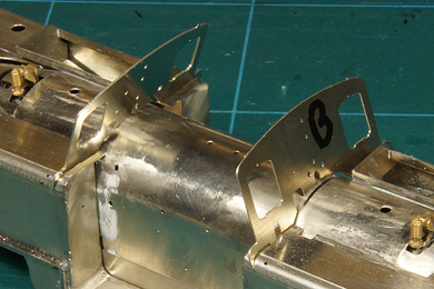
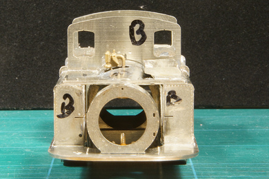
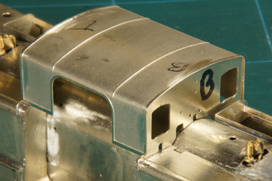
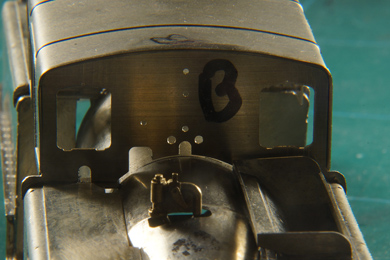
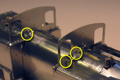
The assembly starts with a decent puzzle [164-168]. There are two cab front sheets, each of which can be fitted in two places in two different orientations, so there are eight ways to place them and only one is the right way. Good luck!
[165] says: "Ensure you get the correct sheet in the correct orientation." Well that sounds pretty encouraging! Thankfully [167] is bit more helpful: "the larger cut outs at the bottom of each sheet are both on the drivers side". The reduces the options to place the sheets to two: now the question is which goes at the bottom end and which goes at the top end of the locomotive. Studying the figures I found that fig 110 showed exactly what I wanted to know. The sheet on the bottom end had an additional large hole on the drivers side which the top end sheet does not have.
This being established I marked them T(op) and B(ottom) on the outsides of the sheets. |
 |
|
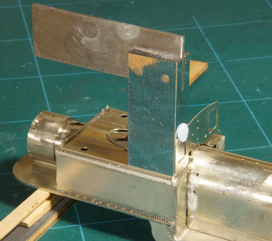 |
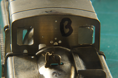
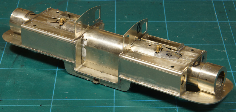
A square does a good job while soldering [169]. This can only be done on the driver's side because the coal bunker on the fireman's side hinders accurate measurement. |
Tacked in place. |
|
 |
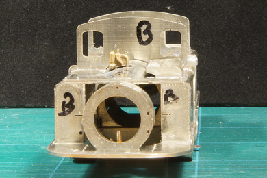 |
The outlining of both sheets is visually checked and checked again from different angles [169].
|
|
 |
And their vertical position is checked.
Finally I measured the distance between the front sheets at tank level on both sides and on roof corner level on both sides and found all four dimensions within a few tenths of a millimetre. Good enough. |
The roof is preformed in the kit, but not yet fully formed to fit. By carefully rolling and forming on steel bars, as I have already demonstrated, I formed the roof to an almost perfect fit [170-174]. Work carefully and take your time. There is no shortcut. See to it that the roof is always held perpendicular to the bar when bending or it will skew. Also mark the roof top which end goes where. Theoretically there should be no difference, the roof is symmetrical to both ends, but your model is never perfect and once you start fitting it really does make a difference. |
|
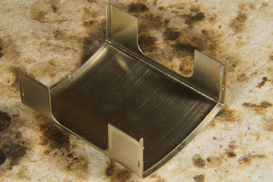 |
Then the inner flanges are soldered in. Again first tack solder and then fill in. The roof has now become relatively rigid and if the difference between the form of the inner flanges and the roof in its natural position is not too big it will simply slide on. |
 |
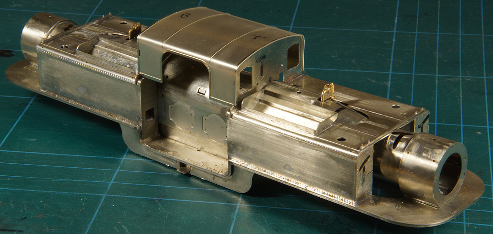
The completed roof slides over the front sheets with only a few tenths of a millimetre to spare. Again: do not solder it in place. It must remain removable. |
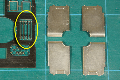 |
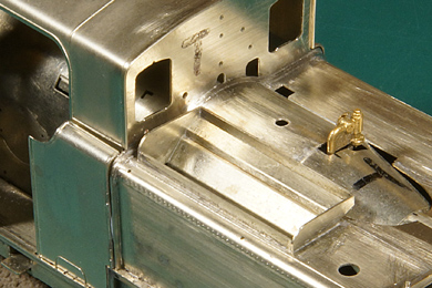
The cab side sheets must be strengthened with an outside fillet. The instructions [175] mention a part number (148) but this number cannot be traced on the etches. It took me a while to find them. I found them on the corner of the etch in which the inner frames of the smokebox were located. |
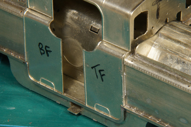 |
After soldering the fillets, the cab side sheets are formed to fit. Before doing so mark each side sheet individually (BF = Bottom end, Fireman's side etc.) to know exactly where each is fitted [177]. No matter how accurate you work, there will be small differences. The curve on the top of the side sheet needs some adjustment. I also found that I needed to do a bit of filing to make them sit over the "shoulder" of the front sheet. File carefully as the side sheets are very thin. Again: do not solder them in place. They must remain removable. The photo was more or less tricked with blue tack ;-) |
 |
 |
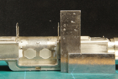
| It seems the boiler ended up in the tank assembly a tad too low, about 0.8 mm or so. Too much to ignore and also too much to fill with solder (left photo). I hoped that the addition of the lower angles (147) [185-188] would resolve this, but once I fitted them (right photo) there was still this same gap. The lower angles had exactly the same form as the bottom end of the front sheets. | |
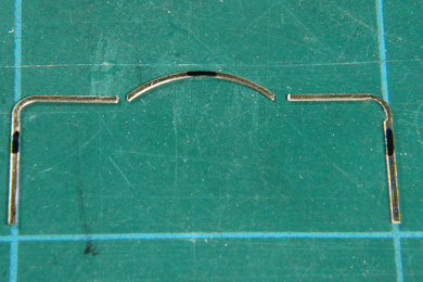 |
To resolve this issue, I cut them in three parts. I soldered the side ends onto the tanks straight away. The middle curve was bent a little more than originally designed, just enough to follow the boiler's contour. |
 |
After soldering every was fine. Having learned from the first angle I cut the second angle in two parts, with the cut behind the coal bunker. In the almost hidden space it will become invisible after painting.
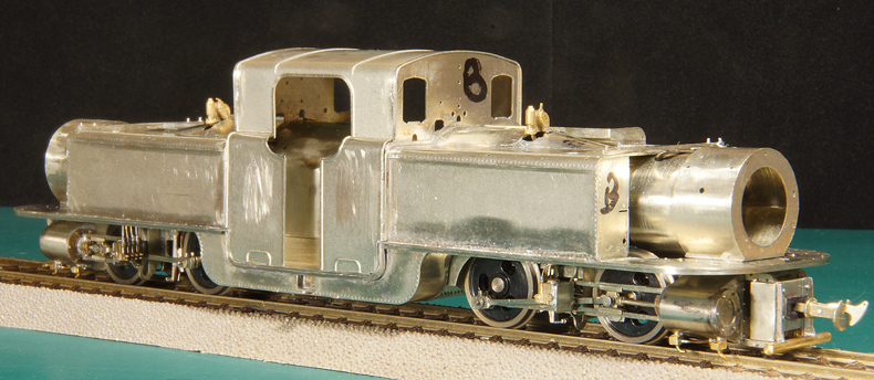
This concludes the "hulk"construction of the superstructure |
The end result fireman's side |
|
Ditto driver's side |
|
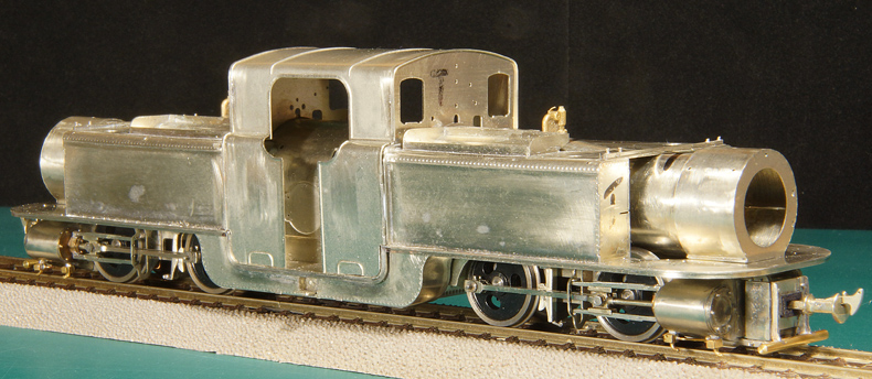
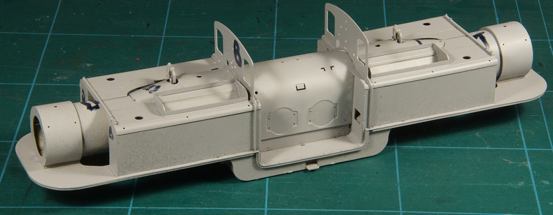
The main construction of the superstructure has now been completed. That said the temptation to push on with detailing should be kept at bay. One absolutely necessary and cruel test needs to be done before detailing can start in earnest: giving the superstructure a base coat. I can almost hear you cry out "What? You shouldn't paint the thing yet because the detailing will require a lot of soldering". Correct, but experience has taught me that
So the best way to get rid of the remaining flaws so far is giving the model a base coat now and inspect it carefully. |
|
Looks good, dunnit? The model was assessed thoroughly and I noted all points of criticism. After that the model was cleaned for corrective work. |
|
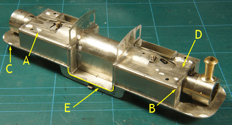
The places that I missed. A. The tabs on the tanks were not fully flush B. On one corner of the tank I forgot a solder fillet C. On the aprons some tabs were not fully flush D. One of the front sheets didn't sit right E. On one side the lower tank valance was still only tacked, I forgot to solder it permanently Nothing bad really and it was all duly corrected with bits of putty and with a bit of extra soldering. |
|

Sign my
GuestBook